| Technical Data | |||
|---|---|---|---|
| Mixing head P1 | Mixing head P2 | Mixing head P3 | |
| Available in three mixing chamber sizes [cm] | 0,2 0,4 0,8 | 1,0 1,6 2,0 | 2,5 4,0 8,0 |
| Discharge capacity [g/s] (Depending on the material, mixing ratio and viscosity) |
0,1 -1,6 | 0,5 -4,0 | 1,2 -30,0 |
| Metering accuracy (Depending on the material, mixing ratio and viscosity) |
.+/-1% | .+/-1% | .+/-1% |
| Control unit | Motion control and visualisation: Metering control: MR40 B&R |
Metering Motion control and visualisation: B&R control: MR40 |
Metering Motion control and visualisation: B&R control: MR40 |
| Operating unit | 10.1″ handheld operating box Optional 5.6″ operating panel |
10.1″ handheld operating box Optional 5.6″ operating panel |
10.1″ handheld operating box Optional 5.6″ operating panel |
| Mixing ratio | from 100:1 to 1:100 infinitely variable |
from 100:1 to 1:100 infinitely variable |
from 100:1 to 1:100 infinitely variable |
| Selectable mixer speed | 1-3,000 U/min infinitely variable |
1-3,000 U/min infinitely variable |
1-3,000 U/min infinitely variable |
| Weight | approx. 12 kg (incl.drive and attachment parts) |
approx. 12 kg (incl.drive and attachment parts) |
approx. 12 kg (incl.drive and attachment parts) |
PRODUCT
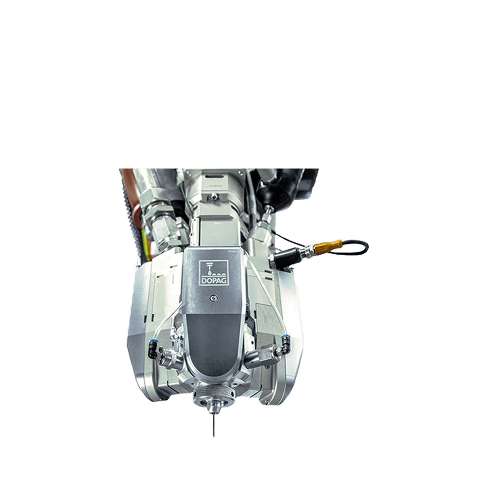
Dynamic mixing head
Dynamic mixing head
Dispensing technology for gasketing, bonding, sealing and potting applications
The dynamic mixing head has a modular design and is available in three forms. Different mixingchamber sizes enable discharge capacities of 0.1 to 30 g/s. The various types of valves andmixing chambers can be combined flexibly in accordance with the required discharge quantityand material properties. This ensures an optimal relationship between the flow rate of thematerial and the application speed.
The nozzle-closing system (NCS) prevents dripping at the nozzle opening. This ensures a smooth transition on the bead and prevents undesired contamination of the components. The NCS moves the drive shaft vertically in the bottom of the mixer, allowing the rotor in the chamber to position on a Teflon seal. This mechanically designed closure prevents the reactive material from being pushed out of the chamber.
Share
 Skip to content


